Introduction
After thinking for well over an year, I finally decided it is time to JUST DO IT! Especially after reaching nearly the end of a carpc project, found the time to work on this project and started gathering componentsOrdered the Sonoff Basic and 4Channel (not the Pro) just to get a flavour of what is expected of me as part of the learning curve in attempting to connect proprietary devices to my own server. All of this is done without the Arduino IDE.

Why not off-the-shelf Apps
Sonoffs work very well with the eWelink Android app, used it for quite sometime before I decided that it is not what I wanted to do. There is very less control over the behaviour. I also don't want to send my data to anybody else's DB, especially,of my house. But for beginners who dont want to do any programming, this is an ideal and cheap platform for entering the smart home space. There's a whole lot of Sonoff devices for every purpose (well, almost)
Reprogramming Sonoff
Devices
For flashing the devices, we need the USB to TTL converter. Got theCP2102 USB 2.0 to TTL UART Serial Converter from Amazon
Also, to connect the Serial converter to Sonoff, we need a 0.1" pitch 5-pin header connector strip, which is also available on Amazon. I got the set of 10.
Firmwares
Did some research on the firmwares availableESPEasy
-Easy to flash and use
-simple enough for starters to understand
-good support
Tasmota
-very comprehensive set of feaatures
-complex flashing process (at least, that's what I thought)
-extensive support and documentation
I got hooked on to the ESPEasy (coz of the perceived ease of use) at the beginning.
Pinouts and connection
The Sonoff basic doesn't have the pins on the board, but the pads are kept ready for accommodating 5 pins. Solder the 0.1" pitch 5-pin header connector to the board and it is ready to be connected to the serial connecter. |
| back to basics |
 |
| After soldering |
 |
| 0.1" (2.54mm) pitch 40 pin header |
 |
| Pins soldered |
Connected the Sonoff to the TTL connector via 4 female to female jumpers, following this pinouts diagram. This is from Jonathan's Sonoff secrets page, a cool resource for sonoff customization.
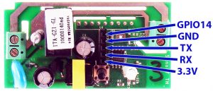
My Serial device has the DTR and 5v (never use this!) pins and are not connected for this purpose.

Serial Connector device preparation
The serial device was not installed properly when connected, so needed drivers. Updated using drivers from this repo. I needed Win7 drivers and updated it from local files saved from the repo. "Scan for hardware changes" and everything was running perfect, I got a COM5. This could be checked in the Device Manager> PortsUploaders and process
Got the uploader ESPEasy_120 stable build from the ESPEasy Wiki.The download comes with the images for 512,1024 and 4096 memory chip versions. The process is started by running the flash.cmd in the folder. The 3 parameters asked are :
1. com port : 5 (from Device manager as above)
2. memory size :1024 (for sonoff basic)
3. build version: 120
The line that runs the actual command is highlighted:
@echo offset /p comport= Comport (example 3, 4, ..) :
set /p fsize= Flash Size (example 512, 1024, 4096) :
set /p build= Build (example 71, 72, ..) :
echo Using com port: %comport%echo Using bin file: ESPEasy_R%build%_%fsize%.bin
esptool.exe -vv -cd nodemcu -cb 115200 -cp COM%comport% -ca 0x00000 -cf ESPEasy_R%build%_%fsize%.bin
pause
Issues
There was no response from the sonoff after the power cycle and it turns out that this is a classic case of the boot error in newer devices coz of the infamous PN25F08B flash memory. Turns out mine is the same too and it needs the DOUT param as mentioned in this discussion.

esptool.exe -vv -cd nodemcu -cb 115200 -cp COM%comport% -ca 0x00000 -bm dout -cf ESPEasy_R%build%_%fsize%.bin
Tried adding the DOUT parameter to the flash.cmd line by editing the command, but still with no results. Also, some FTDIs don't supply enough power to create an AP after the power cycle, so tried powering the device from the mains connected as well, in between all the trials.
Solution
Could've tried one last time with -fm instead of -bm as the below working command, but was reading on the alternatives by this time and thought Tasmota may be not that difficult, after all. Being a python person, seeing the python upload tool in tasmota site also helped in a huge way to decide going for it. Downloaded the Sonoff image and the ESPtool.Installing Python
Installed the python tool by opening a command window in the extracted folder and running
python setup.py install
The above step needs python (2.x or 3.x, I have 2.7) to be installed in the machine, and can be downloaded and installed from www.python.org.
The sonoff.bin was renamed to tasmota.bin and kept in the same directory as the esptool.py.
Flashing
After all those trials, it is better to cleanup and performed an erase, and then flashed. Results belowL:\smart_home\uploaders\esptool-2.2\esptool-2.2>esptool.py --port COM5 erase_flash
esptool.py v2.2Connecting....
Detecting chip type...
ESP8266Chip is ESP8266EXUploading stub...
Running stub...
Stub running...
Erasing flash (this may take a while)...
Chip erase completed successfully in 2.4s
Hard resetting...
L:\smart_home\uploaders\esptool-2.2\esptool-2.2>esptool.py --port COM5 write_flash -fs 1MB -fm dout 0x0 tasmota.bin
esptool.py v2.2Connecting....
Detecting chip type...
ESP8266Chip is ESP8266EXUploading stub...
Running stub...
Stub running...
Configuring flash size...
Compressed 495808 bytes to 341889...
Wrote 495808 bytes (341889 compressed) at 0x00000000 in 30.7 seconds (effective129.2 kbit/s)...
Hash of data verified.
Leaving...
Hard resetting...
 |
| After flash |
Initial Configuration
All was good after the power cycle and the button needs 4 short presses to see an AP from the ESP module. Details of all button presses here.Connected to the Open AP from mobile and going to 192.168..4.1 from a browser in the connected machne. There, we need to set the WiFi settings. Enter the SSID and Password for upto 2 APs (if needed) and leave the others as they are.

Connecting to the device
Find the IP of the device
-in FING (remember to connect to 2.4 GHz network)
-from Router page (under status/clients/dhcp list)
Configuration after the Sonoff connects to the SSID
Main menu will show the state and additional config page buttons
Toggle button toggles ON/OFF
Pushing the button in device also updates the state.
Config Module>
Type: Basic
Everything else: None
Config MQTT>
host/pwd: if already running a server;otherwise leave as is
topic:unique name for the sonoff device (eg:sonoff_1)
The device is ready to be connected to MQTT Apps.
Documentation:
Sonoff Basic
Sonoff 4 Channel